By Patrick Gordon – consultant
There is a basic rule that must be kept in mind with all Hot Water Cylinder (HWC) installations. You are not allowed to have an isolating valve between the HWC and the pressure relief valve.

In most installations that have been correctly plumbed for balanced pressure the pressure reducing valve and the pressure relief valve are situated outside the building to facilitate ease of installation and do a balanced pressure installation. If an isolating valve is now placed near the geyser, this would cut off the path of relief for the geyser. This installation would not comply to SANS 10254.
5.8 Expansion control valve on cold water supply
When an expansion control valve is fitted on the cold water side of the hot water heater, it shall be installed downstream of any isolating valve, gate valve, non-return valve or any other flow-control device.
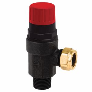
How could I keep the installation as is but make it compliant? This is done easier than what you would think. All you need to do is to fit a pressure relief valve between the geyser and the isolating valve. Just remember that this valve must be fitted over the geyser tray and must be piped out according to the rules set out in SANS 10254.
5.2 Discharge from valves
The discharge pipes from expansion control and safety valves shall
- be of a size not less than the size of the connection to which they are fitted with due consideration to the fact that the maximum length of a run is 4m and for runs that exceed 4m, the size shall be increased over the whole length to a maximum of 9m;
- have three or fewer bends, for each additional bend the maximum drain pipe length shall be reduced by 600mm; all bends shall be a maximum of 45° or formed with a centre-line radius at least five times the diameter of the drain pipe;
- be so installed that
- they incline downwards continuously to their outlet,
- drainage of both valve and piping is ensured,
- blockage due to freezing or foreign objects is prevented,
- when flow occurs from them, the flow can be readily observed with the minimum risk of injury or damage due to steam or hot water,
- they are never joined together,
- each is led to a discharge point which is visible outside the building and in a position where the discharge from the pipe will not cause a nuisance and also cannot be blocked,
- water traps which could prevent the free return of air into the system do not develop,
- in the case of safety valves, always be of metal and be inclined downwards away from the valve;
- be used for conveyance of water resulting from the normal expansion of heated water and shall discharge to the atmosphere in a position where the discharge is readily discernible but shall not inconvenience the building’s occupants or cause damage to the building.
- The relief valve must also be sized according to the pressure rating of the pressure reducing valve.
4.3.2 Pressure rating of the system
The rated pressure of the system shall not exceed a static pressure of 600 kPa (see SANS 10252-1) and the pressure control valves and expansion control valves used in the system shall have the same pressure rating. This pressure rating may be less than the rated pressure of the storage water heater but shall never exceed it.
From these extracts of SANS 10254 it is clear that there are several contributing factors to keep in mind when deciding where to position the expansion relief valve in an installation. By using the information at your disposal, you can make small changes to a non-compliant installation and make it compliant.
For any further information on this topic please contact the writer: PA Gordon on patrickg@splashworks.co.za.
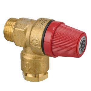
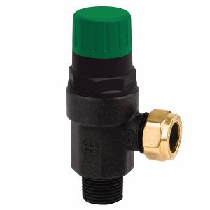
Images are by courtesy of Advanced Valves and Calafrica. Extracts are from SANS 10254.
Register for free to gain access the digital library for Plumbing Africa publications